Showing posts with label 3D Studio Max Tutorial. Show all posts

Tuesday, February 22, 2011

Stage 7: Setup Views

Introduction

Key 3D uses ONE camera for still views. This is tied into Image Object functionality where images of people and trees and shrubs are mapped onto planes and 'look at' the camera. If each view had a separate camera, then the Image Objects would not always be facing the correct camera. Key 3D View Manager is used to setup and manipulate the camera and keeps view settings as 'views' in a list. The following routine explains how to setup views using Key 3D View Manager

Download Sample Data

In order to follow this tutorial, you may want to use the supplied files. Please read the sample data instructions before downloading.
AutoCAD Drawing files: dwg_files.zip (784kb)
3ds Max Scene files: scene_files (7.8mb)


7.1 Create and configure Key 3D Camera

  • Carry on from the previous scene or open ACAD to 3D Stage 7.max
  • In the Top viewport create a Target Camera with the target facing the centre of the site
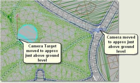
  • Move the target to approximately ground level and the Camera, again, to approximately ground level in the position shown below

  • Open Key 3D Camera and press Pick Camera
  • Pick the camera in the Top viewport. This configures the camera for use with Key 3D Image Objects and mini-renderers

Note that the camera is renamed Camera_Key3D
  • Right click in the Left viewport and type C on the keyboard to change the view to the Camera view. Note also that the name is evident in the top left of the viewport and that Camera_Key3D is now displayed on the button. This shows that a camera has been configured for use as the Key 3D Camera


7.2 Setup views

  • Select the Camera Target in the Top viewport
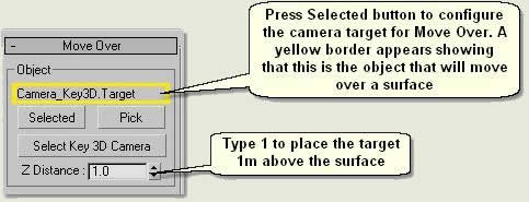
  • Open Key 3D Move Over and press Selected. The name Camera_Key3D.Target appears under Object and a yellow border displays that this is the object that will move over the surface
  • Change the Z Distance to 1. This places the camera target 1m above the surface
NOTE: Sometimes the object has to be moved slightly in the Top viewport before a reading is given in the Z Height spinner

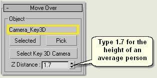
  • Repeat this process for the Key 3D Camera

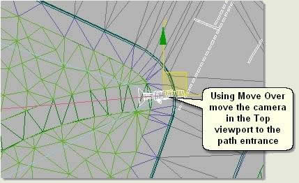
  • In the Top viewport move the Key 3D Camera to the path entrance

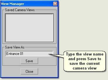
  • Open Key 3D View Manager
  • Press Save Camera View. In the Save View dialog type Entrance 01 and then Save

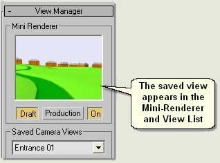
  • The view appears in the Mini-Renderer and View list

  • Repeat the above procedure for all the entrance points so that 4 named views are created
  • Finally, move the camera target to the centre of the site - where the small play area meets the path - and move the camera up to give an overview of the site
  • Create 4 more views named Overview SW, Overview SE, Overview NW and Overview NE to make 8 views in all
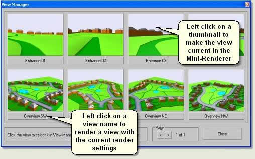
  • Press Browser to open the View Manager Browser

  • Left click on a view name to render the view with the current render settings
  • Left click on a thumbnail to make the view current in the Mini-Renderer
  • To change the view in the viewport to the same as the Mini-Renderer press Copy to Camera

Stage 6: Lighting and Shadows

Introduction

Lighting outdoor scenes involves the setup of a Sunlight or Daylight system, together with ambient light. The sunlight or daylight system gives the main illumination and shadows, with ambient light (light that is 'global' in nature, which affects all objects and is reflected from one to another) provided by using one (or more) of a number of techniques. Techniques for providing ambient light range from environment dialog settings, placement of omni lights, use of a Skylight or a 'light dome' which shines multiple spotlights on the scene and gives soft shadows around objects. This tutorial uses Key 3D Sunlight and Shadows to automatically setup a Sunlight System with some environment settings and including the use of a Key 3D Light Dome for added natural ambient light
NOTE: Lighting setup should be complete, apart from final tweeking, before assigning materials to objects because lighting affects how materials display and render (especially image mapped materials)

Download Sample Data

In order to follow this tutorial, you may want to use the supplied files. Please read the sample data instructions before downloading.
AutoCAD Drawing files: dwg_files.zip (784kb)
3ds Max Scene files: scene_files (7.8mb)


6.1 Insert Sunlight System and Light Dome

  • Carry on from the previous scene or open ACAD to 3D Stage 6.max

Insert Sunlight System

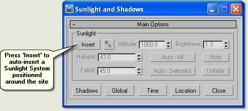
  • Open Key 3D Sunlight and Shadows and Press Insert Sunlight. A Sunlight System is inserted in the scene and auto-positioned around the site

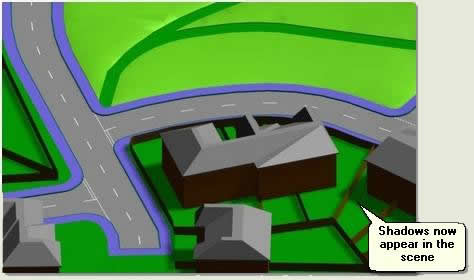
  • Render the User viewport to see the shadows

Insert Key 3D Light Dome for Global Light

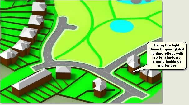
Use of a light dome is a good alternative to a Skylight or other lights such as omni lights placed in the scene. A light dome arranges multiple spotlights around the site and uses shadow mapping which is far faster than ray-traced shadow solutions. Often referred to as 'fakosity' the effect gives soft shadows around and under objects and simulates natural exterior lighting
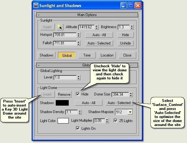
  • Key 3D Sunlight and Shadows > Global dropdown dialog
  • Press Insert. This automatically inserts a light dome around the site. To optimise the size of the dome select Surface Context and press Auto-Selected
  • To view the light dome uncheck Hide, then check again to hide the light dome


NOTE: The Key 3D Template scene has the Ambient Color changed from black to mid grey on the Environment dialog. Check this colour at this stage and alter if needed to lighten or darken the overall lighting in the scene. However, do not lighten to much as this can have the effect of reducing contrast and 'flattening' the scene


6.2 Alter settings for light and shadows

Experiment with the following settings to create the optimum lighting effects for the scene. These settings can be re-visited when materials have been applied to further enhance the output renders

General Sunlight settings

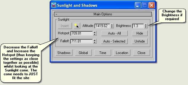
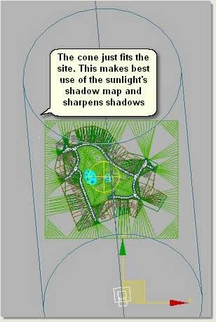
  • Reduce the Hotspot and Falloff so that the sunlight just covers the site: Select Sunlight_Key3D and reduce the Falloff or increase the Hotspot whilst looking at the sunlight cone in the Top viewport. This optimises the shadow map settings giving the ability to emulate ray-tracing shadows if needed
  • Change the Brightness value if required


Global Light Settings

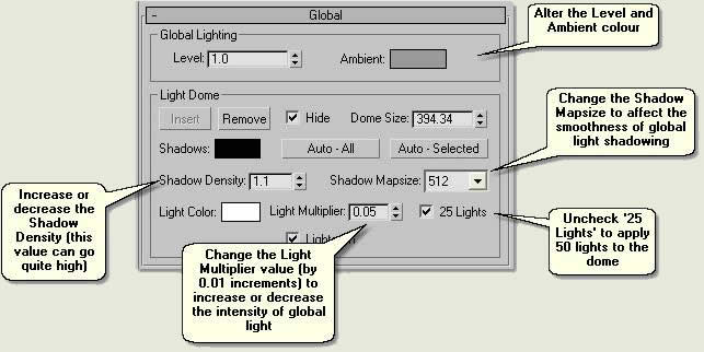
  • Alter the Level and Ambient colour
  • Change the Light Multiplier value (by 0.01 increments) to increase or decrease the intensity of global light
  • Increase or decrease the Shadow Density value. Note that this value can go quite high (up to 3 or 4)
  • Change the Shadow Mapsize to affect the smoothness of global light shadowing
  • Uncheck '25 Lights' to apply 50 lights to the dome

Shadow settings

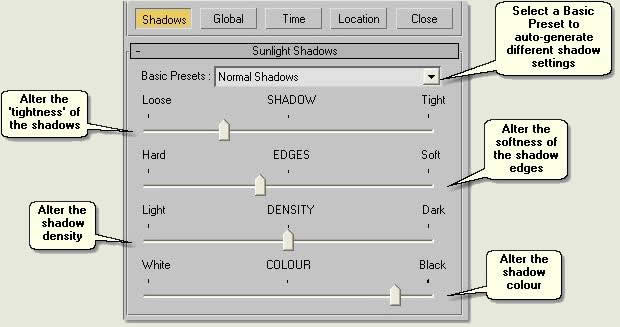
  • Press Shadows to open the Shadows dropdown dialog
  • Select a Basic Preset, either Normal, Strong or Soft to auto-generate the required type or fine tune as follows:
  • Under SHADOW alter the tightness of the shadows
  • Under EDGES alter the softness of the shadow edges
  • Under DENSITY alter the shadow density
  • Under COLOUR alter the shadow colour from white to black


6.3 Animate the Sunlight

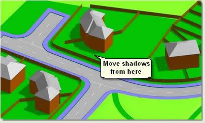
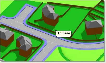
Animating the sunlight throughout the day is a quick way to achieve the required shadows based on the time of day
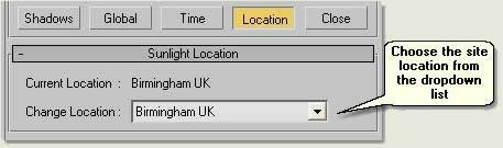
  • Press Location

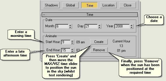
  • Press Time
  • Choose a date, a start time and an end time and press Create
  • Move the Time Slider to position the Sunlight in the sky and test render to find the best solution for the scene. The Current Hour is updated as the Time Slider is moved
  • When the Sunlight is in the optimum position press Remove to remove the animation

NOTE: A common mistake is to leave animation on the Sunlight when animating objects such as cameras. This will animate the sun as the camera moves. So, unless a shadow study animation is being made, always remove the animation when the optimum sun position has been achieved and use the animation tools mainly as a quick method of positioning the Sun


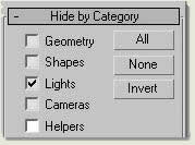
  • Finally, on the Display Panel Hide by Category the Lights. This will help when zooming to the site as the Sunlight will not be included

Stage 5: Create Houses, Roadlines and Fences

Introduction

These elements of the scene are classed as 'Objects'. Objects are items that sit on the landform terrain (lamp posts, bollards, houses etc) or conform to its surface (fences for example). They are usually positioned in AutoCAD using blocks (lamp posts, bollards etc) or lines (closed polygons for house outlines, road lines or polylines for fence lines). This stage describes the process for creating houses (including roofs), fences and road lines

Download Sample Data

In order to follow this tutorial, you may want to use the supplied files. Please read the sample data instructions before downloading.
AutoCAD Drawing files: dwg_files.zip (784kb)
3ds Max Scene files: scene_files (7.8mb)

5.1 Create Houses

The polylines for houses and roadlines need to be imported so that they are created as separate entities. This is because the houses need to be placed at different heights on the surface (automatically using Key 3D Move Over) and the roadlines need to be configured individually using Key 3D Roadlines. To import these lines as individual entities the Legacy AutoCAD Import option is used
Firstly, just the layers required for import need turning On in AutoCAD
  • Open Project for 3D 03.dwg in AutoCAD and turn all layers Off apart from O_Roadline and O_Houses
  • Save the drawing as Houses and Roadlines.dwg
  • Close AutoCAD
  • Carry on from the previous scene or open ACAD to 3D Stage 4.max in MAX/VIZ
  • File > Import. Choose Files of Type: Legacy AutoCAD (*DWG) and select Houses and Roadlines.dwg
  • Check Merge objects with current scene when prompted and press Ok
  • On the Import AutoCAD DWG File dialog check just Skip off and frozen layers and make sure Weld is unchecked
  • Press Ok to import the houses and roadlines
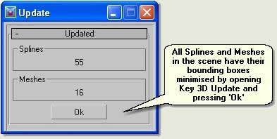
The houses and roadlines will have rather large bounding boxes (sometimes an issue with data imported from AutoCAD). To minimise the bounding boxes of all objects do the following:
  • Open Key 3D Model Objects dropdown Menu > Update
  • Press Ok and notice that now when selected any object's bounding box fits the object tightly
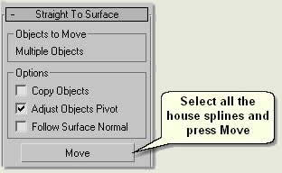
  • In the User viewport select all the house splines using the Select by Name dialog and open Key 3D Straight to Surface
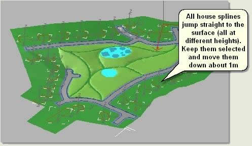
  • Keep options as default and press Move. The house splines will all move to the surface
  • Keep them selected and move them all down 1m using Move Transform Type-in and Offset:World. This makes up for any gaps between house and sloping land
NOTE: The house splines could have been moved to their correct heights and included in the spline model from which the terrain was created. This would give a correct 'platform' for each house. The house splines plus any level area boundaries (for paths and adjoining areas around a houses) can be included. Then, the house splines would sit on a level area. In this case they are being used for broad brush context modelling and so a more rudimentary method is being used
  • Keep the house splines selected and apply an Extrude modifier at an Amount of 7
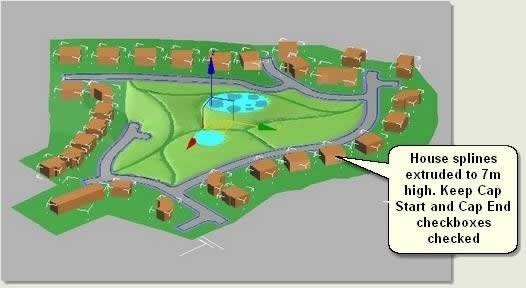
  • Keep the houses selected and use Edit > Clone dialog to Copy clone them
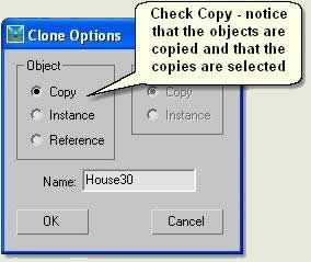
The houses are copied and the copies are selected
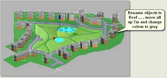
  • Keeping the copies selected use the Rename dialog to rename the copies Roof01 to Roof29
  • Keep the roofs selected and move them all up 7m using Move Transform Type-in and Offset:World
  • Change the colour to grey

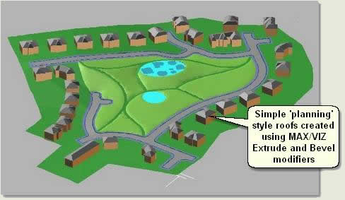
  • Again, keeping the roofs selected, in the Modify Panel remove the Extrude modifier from all the roof objects (press the dustbin icon below the modify stack window)
  • Apply a Bevel modifier to all the roofs with the following settings:
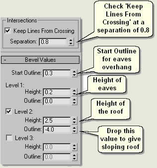

  • Select all houses and roofs and Convert to Editable Mesh
  • Finally create a Group from all Houses and Roofs called 'Houses'


5.2 Create Roadlines

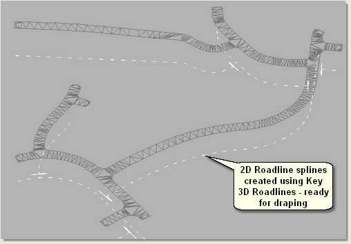
Roadlines are created using Key 3D Roadlines which produces 2D segmented roadlines. Roadline presets for length, width and spacing can be applied and offsets adjusted to butt up to other roadlines. The roadlines can be created as straight or curved 2D splines before using Key 3D Drape to drape the lines over the road surface. Finally the closed roadline segments are extruded slightly to produce 3D roadlines conforming to the surface
NOTE: Continuous roadlines (not applicable in this example) are created using spline sub-object editing - the Outline operation in spline sub-object mode
  • Carry on from the previous scene or open ACAD to 3D Stage 5a.max
  • Select all the Roadbaseline splines (25) and Surface_B_Road and Isolate Selection
  • In the Top viewport zoom to the junction shown below and select Road baseline16
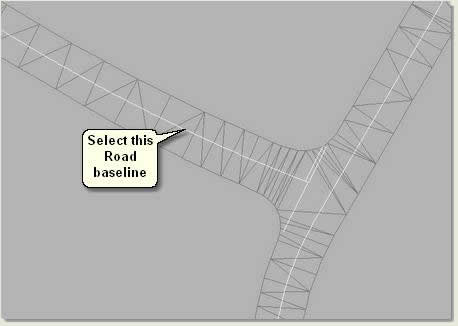
  • Open Key 3D Roadlines The name of the spline appears under Name
  • Press Preset Browser and select Preset 1008
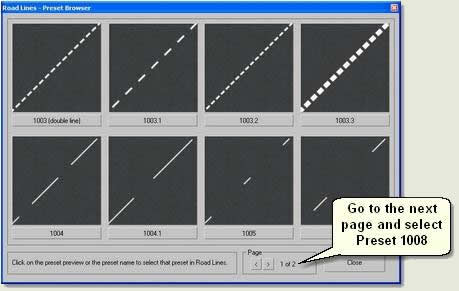
  • Press Apply to apply the roadline preset to the base roadline
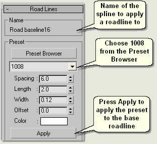
  • Zoom to the junction and increase the Offset amount so that the roadline butts up to the junction lines
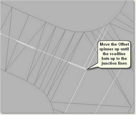
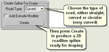
  • When satisfied that the roadline is in the correct position choose the Road Type: 'Curved' under Create Spline For Drape
  • Press Create to create a 2D roadline ready for draping. If the Road Type is curved or circular a progress message appears - this is because extra vertices are added on the roadline segments to give a curved segmented roadline
  • Delete the base roadline and repeat the routine for the junction lines. These use the Preset 1009
  • Once created, some segments may be removed in spline sub-object mode
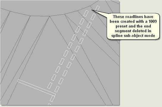
NOTE: Roadlines must be created separately and cannot be attached together prior to applying a preset
  • Repeat this procedure for all remaining roadlines, creating 2D splines with 1008 (curved) and 1009 (straight) presets and making sure that all roadlines butt up to each other using the Offset spinner
  • Attach all the roadlines together to make one editable spline and rename Roadlines
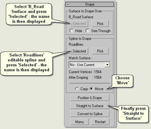
  • Select B_Road Surface and open Key 3D Drape
  • Under Surface to Drape Over press Selected. B_Road Surface is then displayed
  • Select Roadlines editable spline and under Spline to Drape press Selected. Roadlines is then displayed
  • Keep the Match Surface settings on No - Use Current
  • Select Move so that the spline will move straight up to the surface automatically
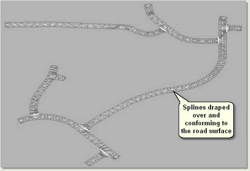
  • Finally, press Straight to Surface to drape the roadline splines over the road surface

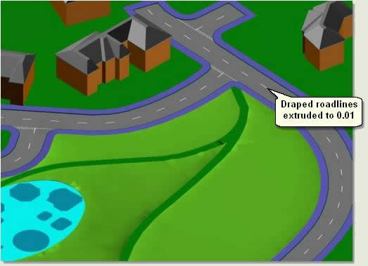
  • Apply an Extrude modifier at a height of 0.01. This will create 3D roadlines conforming to the road surface


5.3 Create House Fences

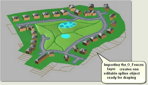
The house fence lines can be imported using the more comprehensive AutoCAD DWG/DXF Import Options dialog. This will import the lines as one object (ie not separate lines). This is what is required here as the lines will be draped over the surface in one operation using Key 3D Drape
  • Carry on from the previous scene or open ACAD to 3D Stage 5b.max
  • File > Import. Choose Files of Type: AutoCAD Drawing (*DWG,*DXF) and select Project for 3D 03.dwg
  • On the AutoCAD DWG/DXF Import Options dialog Layers Tab check O_Fences
  • On the Geometry Tab check Weld and keep all other checkboxes unchecked
  • Press Ok and notice that one object (ie not separate splines) has been imported called 'Layer:O_Fence'.
  • Rename the fence lines to 'O_Fence'

  • Select Surface_B_Site and open Key 3D Drape
  • Under Surface to Drape Over press Selected. Surface_B_Site is then displayed
  • Select O_Fence editable spline and under Spline to Drape press Selected. O_Fence is then displayed
  • Keep the Match Surface settings on No - Use Current
  • Select Move so that the editable spline will move straight up to the surface automatically
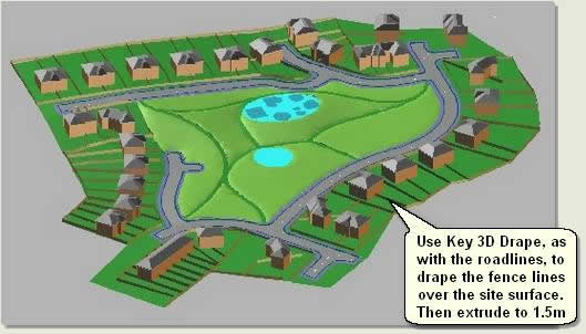
  • Press Straight to Surface to drape the fence splines over the site surface
  • Finally, apply an Extrude modifier to a height of 1.5
  • Check how many faces exist in the scene using File > Summary Info dialog
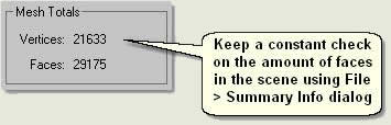
TIP: Select and right click over any object and select Properties to display information about objects including the face count and name of material assigned

Stage 4: Create Kerbs

Introduction

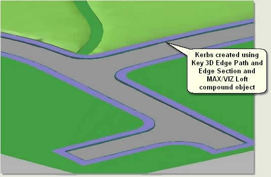
In general an edge is created where one surface meets another. An edge could be a surface level edge, a kerb, a retaining wall, steps or terrace. Edges are often created using the Loft compound object instead of a simple extrusion to take advantage of the loft mapping parameters. The Loft mapping parameters enable kerb or brick materials to follow the curves of an edge as they do in the real world
In this example a kerb is created using Key 3D Edge Path and Key 3D Edge Section

Download Sample Data

In order to follow this tutorial, you may want to use the supplied files. Please read the sample data instructions before downloading.
AutoCAD Drawing files: dwg_files.zip (784kb)
3ds Max Scene files: scene_files (7.8mb)


4.1 Create a path for the kerb

  • Carry on from the previous scene or open ACAD to 3D Stage 3b.max
  • Select Surface_ B_Road and Isolate Selection
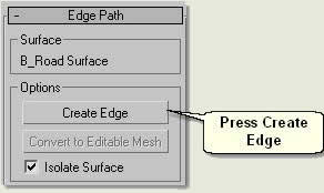
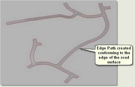
  • Open Key 3D Edge Section and press Create Edge

  • When the Create Edge dialog pops up select (as always) Linear and type Kerb Path in the Curve Name text box


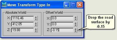
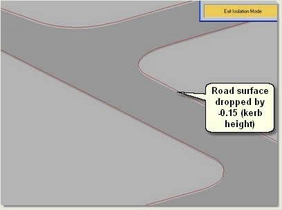
Select Surface_B_Road again and move the surface down on the Z axis -0.15


4.2 Create a kerb loft

  • Open Key 3D Edge Section dialog
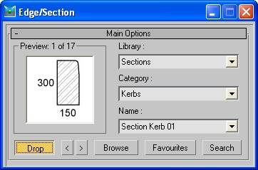
  • Press Browse and select Section Kerb 01
  • Press Drop and in the Top viewport place the Section at the top left of the site

NOTE: Placing all sections for lofts or other shapes for bevel profiles etc at the top left of the site, away from the site geometry, is a good habit. Sections and profiles are then available in an easy to access place for re-use at any time
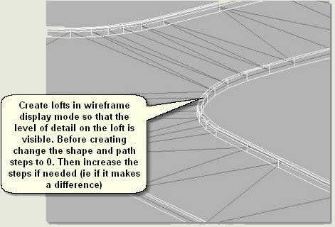
  • Make the display type Wireframe. This helps when optimising the loft path and shape steps
  • Select Kerb Path and open Key 3D Edging dropdown > Loft
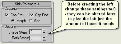
  • On the Skin Parameters rollout change the Shape Steps to 0 and the Path Steps to 0

  • On the Creation Method rollout press Get Shape.


  • On the Skin Parameters rollout increase the Shape Steps and Path Steps to see if they alter the smoothness of the kerb. In this instance it does not, so leave the settings as they are at 0
  • Rename the loft Loft Kerb
TIP: Naming in this way ensures that any lofts are easily identified in the scene. When materials have been properly mapped to the kerb (later) it can then be renamed and converted to an editable mesh. This procedure ensures objects uses less system resources when creation, modification and material application has been completed
  • Right click over the loft and select Properties. The kerb loft should have about 7000 to 8000 faces. This is acceptable as the loft is the only loft in the scene and is a main feature.
TIP: Always approach the creation of lofts in this way ie keeping a tight hold over the number of faces. Measures to reduce the amount of faces should be taken before loft creation when determining the amount of vertices on the splines used to create the landfom terrain. However, the shape and path sub-objects of the loft can be accessed on the Modify Panel after creation and number of vertices reduced if required
NOTE: To change other parameters on the loft such as the orientation (the loft sometimes is inverted) or the position of the loft on the path Ref: Key Fundamentals / Working with Objects

Twitter Delicious Facebook Digg Stumbleupon Favorites More

 
Powered by Blogger